The Navigation Computer: A Practical Example
Take the following situation:
You are in a Warrior PA 28.
TAS is 100 knots.
Heading of 000°(T).
The forecast W/V is 240/30.
What will be your track and ground speed?
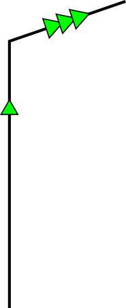
Start by drawing out your Triangle of Velocities.
On a piece of paper (graph paper, ideally), draw in the Air Vector. It will have a direction of 000°(T) and a vector length equivalent to 100 knots (say, 100 mm).

Now draw in the Wind Vector. It was 240/30.
Remember, it is from 240°. It will actually point in the direction 060°(T).
Whatever units you used in proportion to 100 knots TAS (100 mm), draw the length of the Wind Vector in the same units (30 mm).
Now join the start of the Air Vector to the end of the Wind Vector to establish the resultant – the Ground Vector:-
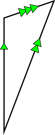
When you do that on your piece of graph paper, if you measure the track with a protractor you will find that it is 012° and if you measure the length of the ground vector you will find a vector length equivalent to 118 knots.
What this is telling you is that if you fly a heading of 000°(T) at a TAS of 100 knots in a wind of 240/30, your path over the ground will actually be a track of 012°(T) at a ground speed of 118 knots.
It would be a bit long-winded if every time you wanted to fly, you had to start doing little scale drawings on graph paper. There has to be a quicker way. There is. It is called the Navigation Computer - but using the Wind Face this time.
Same situation:
You are in a Warrior PA 28.
TAS is 100 knots.
Heading of 000°(T).
The forecast W/V is 240/30.
What will be your track and ground speed?
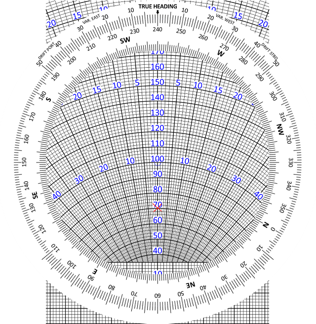
Start off by putting the W/V on the Navigation Computer.
Rotate the wind face to bring 240 up to the index (the 12 o’clock position).
Put any convenient datum to measure from (say 100 knots) under the blue circle in the centre of the wind face. (Alternatively, you can use the ‘graph paper’ square grid at the bottom of the slide).
Now plot downwards (in the 6 o’clock direction).
Mark off 30 knots on the wind face.
That is the Wind Vector plotted. Now for the Air Vector.
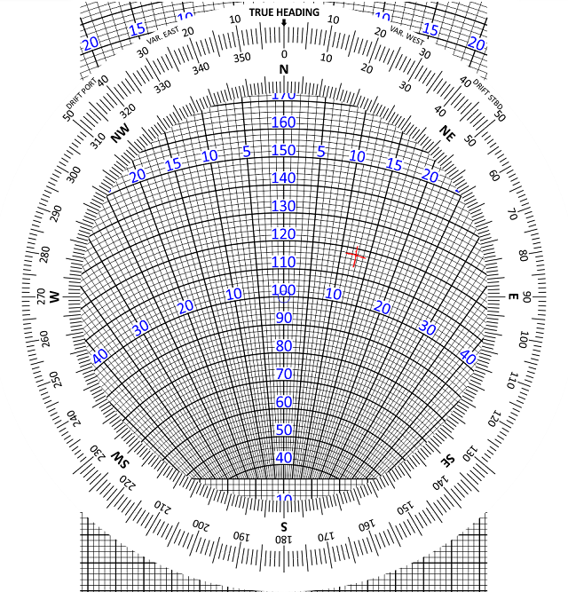
Rotate the wind disc to put the Heading (000°) against the true heading index (12 o’clock position)
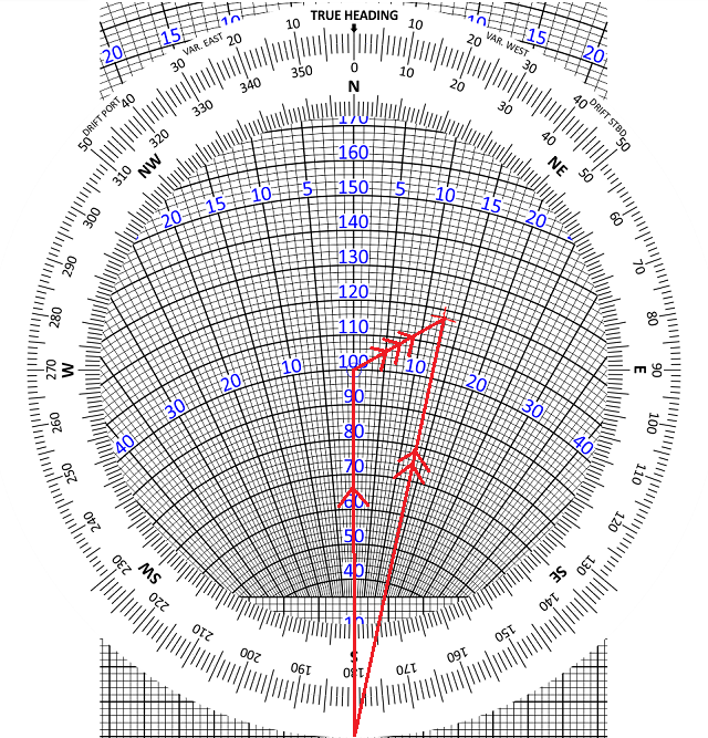
Move the slide to put your TAS (100 knots) under the blue circle in the centre. It should now look like this
Now look where the wind mark is positioned. It is about 12 degrees right of the centre line. This means that you have 12 degrees of starboard drift. Your heading is 000°, so your track is 012°.
The ground speed is obtained by reading it off against the radial arcs. In the above example, it is 118 knots.
These are the same answers that we got by scale drawing.
All that the Navigation Computer has done is to produce an analogue model of our scale drawing.
The centre line is the Air Vector, pointing 000°, with a length of 100 knots TAS.
It is joined to the Wind Vector, which you have plotted downwind yourself.
The resultant vector, which connects the start of the Air Vector to the end of the Wind Vector, is the Ground Vector. It tracks up the 12° starboard drift line to give Track direction and ground speed vector length.
Next: Uses of the Wind Face
© 2022 terms of use privacy policy
